- 您现在的位置:买卖IC网 > Sheet目录1991 > CS43L22-CNZR (Cirrus Logic Inc)IC DAC W/HDPN & SPKR AMPS 40-QFN
DS792F2
15
CS43L22
Confidential Draft
3/4/10
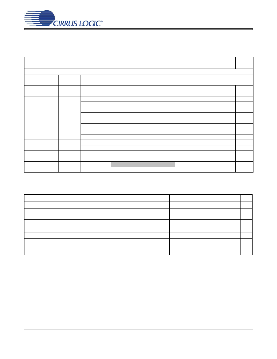
LINE OUTPUT VOLTAGE LEVEL CHARACTERISTICS
Test conditions (unless otherwise specified): Input test signal is a full-scale 997 Hz sine wave; measurement bandwidth is 20 Hz
to 20 kHz; Sample Frequency = 48 kHz; Test load RL = 10 kΩ, CL = 10 pF (see Figure 2); “Required Initialization Settings” on
page 32 written on power up.
COMBINED DAC INTERPOLATION & ON-CHIP ANALOG FILTER RESPONSE
9.
Response is clock dependent and will scale with Fs. Note that the response plots (Figures 22 and 25 on
page 63) have been normalized to Fs and can be de-normalized by multiplying the X-axis scale by Fs.
10. Measurement Bandwidth is from Stopband to 3 Fs.
Parameters
VA = 2.5V
Min
Typ
Max
VA = 1.8V
Min
Typ
Max
Unit
AOUTx Voltage Into RL = 10 kΩ
HP_GAIN[2:0]
Analog
Gain (G)
VHP
000
0.3959
1.8 V
-
1.34
-
0.97
-
Vpp
2.5 V
-
1.34
-
0.97
-
Vpp
001
0.4571
1.8 V
-
1.55
-
1.12
-
Vpp
2.5 V
-
1.55
-
1.12
-
Vpp
010
0.5111
1.8 V
-
1.73
-
1.25
-
Vpp
2.5 V
-
1.73
-
1.25
-
Vpp
011 (default)
0.6047
1.8 V
-
2.05
-
1.41
1.48
1.55
Vpp
2.5 V
1.95
2.05
2.15
-
1.48
-
Vpp
100
0.7099
1.8 V
-
2.41
-
1.73
-
Vpp
2.5 V
-
2.41
-
1.73
-
Vpp
101
0.8399
1.8 V
-
2.85
-
2.05
Vpp
2.5 V
-
2.85
-
2.05
-
Vpp
110
1.0000
1.8 V
-
3.39
-
2.44
-
Vpp
2.5 V
-
3.39
-
2.44
-
Vpp
111
1.1430
1.8 V
(See (Note 8)
2.79
Vpp
2.5 V
-
3.88
-
2.79
-
Vpp
Parameters (Note 9)
Min
Typ
Max
Unit
Frequency Response 10 Hz to 20 kHz
-0.01
-
+0.08
dB
Passband
to -0.05 dB corner
to -3 dB corner
0
-
0.4780
0.4996
Fs
StopBand
0.5465
-
Fs
StopBand Attenuation (Note 10)
50
-
dB
Group Delay
-
9/Fs
-
s
De-emphasis Error
Fs = 32 kHz
Fs = 44.1 kHz
Fs = 48 kHz
-
+1.5/+0
+0.05/-0.25
-0.2/-0.4
dB
发布紧急采购,3分钟左右您将得到回复。
相关PDF资料
CS4461-CZZR
IC ADC PSR FEEDBACK 24-TSSOP
CS5340-CZZ
IC ADC AUD 101DB 200KHZ 16-TSSOP
CS5340-DZZR
IC ADC AUD 101DB 200KHZ 16-TSSOP
CS5341-DZZ
IC ADC AUD 105DB 200KHZ 16-TSSOP
CS5342-CZZ
IC ADC AUD 105DB 200KHZ 16-TSSOP
CS5345-CQZ
IC ADC AUD 104DB 200KHZ 48-LQFP
CS5345-DQZ
IC ADC AUD 104DB 200KHZ 48-LQFP
CS5346-CQZR
IC ADC AUD 103DB 200KHZ 48-LQFP
相关代理商/技术参数
CS43L23-CWZR
功能描述:IC DAC W/HDPN & SPKR AMPS 40-QFN 制造商:cirrus logic inc. 系列:* 零件状态:Not For New Designs 标准包装:6,000
CS43L36-CNZ
功能描述:IC-LOWPOWERHIGHPERFORMANCE HEADP 制造商:cirrus logic inc. 系列:* 零件状态:在售 标准包装:490
CS43L41
制造商:CIRRUS 制造商全称:Cirrus Logic 功能描述:Low Power 24-Bit, 96 kHz DAC with Volume Control
CS43L41-KZ
制造商:Rochester Electronics LLC 功能描述:- Bulk
CS43L42
制造商:CIRRUS 制造商全称:Cirrus Logic 功能描述:Low Voltage,Stereo DAC With Headphone Amp
CS43L42-EP
制造商:Cirrus Logic 功能描述:
CS43L42-KZ
功能描述:数模转换器- DAC IC Low PWR Str DAC w/Hdphn & Line Amp RoHS:否 制造商:Texas Instruments 转换器数量:1 DAC 输出端数量:1 转换速率:2 MSPs 分辨率:16 bit 接口类型:QSPI, SPI, Serial (3-Wire, Microwire) 稳定时间:1 us 最大工作温度:+ 85 C 安装风格:SMD/SMT 封装 / 箱体:SOIC-14 封装:Tube
CS43L42-KZR
功能描述:数模转换器- DAC IC Low PWR Str DAC w/Hdphn & Line Amp RoHS:否 制造商:Texas Instruments 转换器数量:1 DAC 输出端数量:1 转换速率:2 MSPs 分辨率:16 bit 接口类型:QSPI, SPI, Serial (3-Wire, Microwire) 稳定时间:1 us 最大工作温度:+ 85 C 安装风格:SMD/SMT 封装 / 箱体:SOIC-14 封装:Tube